

By Robbin Laird
Because the F-35 has been built from the outset on a digital thread production approach and foundation, the program can incorporate, and contribute to a broader set of industrial transformations, known as Industry 4.0.
In other words, the F-35 can produce an innovative combat aircraft but it is part of a much broader industrial transformation process designed to be able to leverage that transformation process.
It is a two way street.
The F-35 approach enables Industry 4.0 in the defense domain but also draws from a much broader industrial transformation process as well.
Prof. Dr.-Ing. Thomas Bauernhansl, director of Fraunhofer Institute for Manufacturing Engineering and Automation IPA, provides a perspective on the advance of digitalization and the changing face of production in the context of Industry 4.0.
There are many different interpretations of Industrie 4.0. Professor Bauernhansl, what’s your view?
Industrie 4.0 is about complete digital connectivity: between the means of production; their virtual representations, or digital twins; and the employees involved in that process.
This facilitates revolutionary developments in production operations by allowing highly qualified, flexible workers to collaborate with intelligent cyber-physical systems in smart processes.
While Industrie 4.0 has not yet found its way into all companies, it is a trend that’s being talked about throughout Germany, and we expect this to trigger a revolutionary shift in the way we approach value creation – a fourth industrial revolution. 1
The digital thread production approach of the F-35 program is congruent with the trend lines associated with Industry 4.0.
During my most recent discussion with Don Kinard, Senior Fellow for Lockheed Martin’s F-35 Production, he underscored how important developments in Industry 4.0 were for the evolution of F-35 production processes.
This discussion took place in October 2018.
In effect, the F-35 as a military aircraft has a very different approach to what the supply chain actually means compared to a legacy production military combat aircraft.
It is not just about what the production of the aircraft; it is about the evolution of the aircraft and its sustainment in a dynamic feedback process.
It is a software upgradeable aircraft produced and maintained through a digital process.
As Kinard explained the approach as applied to F-35 production:
“We are shifting significantly from manual collection of data to automated data which allows us to see the entire production process.
“And that allows us not simply to capture and automate descriptive data but apply analytics to derive predictive and prescriptive information as well.
“We increasingly will be able to see into the field supply chain requirements and combine this with the demand side from operations.
“The supply chain with regard to a production process is largely stable but the demand side from the field is not so predictable and as we can get greater understanding of both demand sides and combine them, we can get better understanding and control of the broader supply chain process.
“And this ability will go up as we marry the enterprise systems, including ALIS (the sustainment digital system) with our ERP, our PLM, and our MES systems to create the future vision for the Intelligent Enterprise.
“Industry 4.0 for us is about automating all of the data in the factory as well as enterprise data such as cost, quality, and schedule performance.
“And it is about automated data as I said not just for descriptive data but prescriptive data as well.
“And we will then be able to look at demand fluctuations across the board to manage the supply chain.”
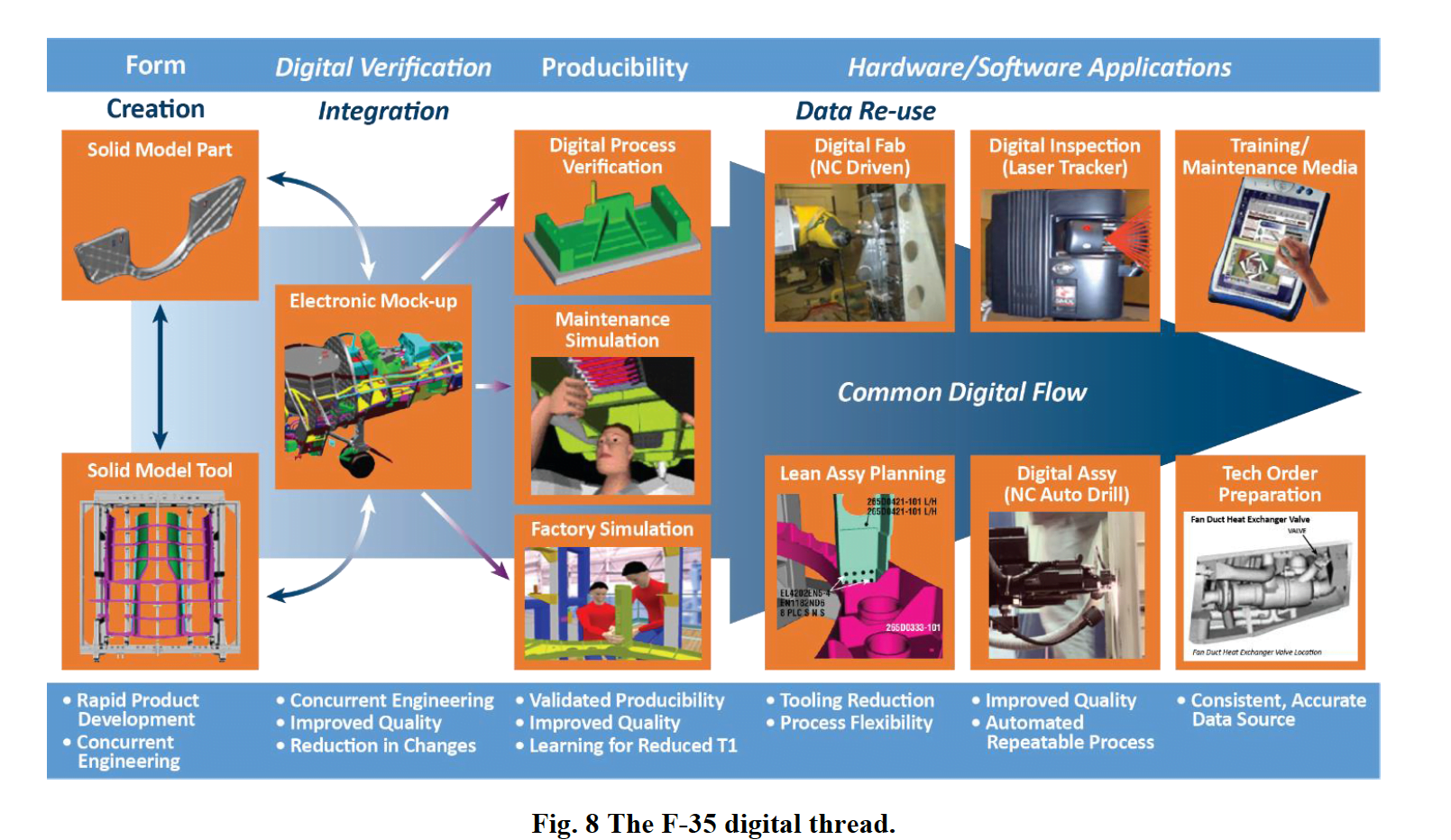
In a recent paper which he delivered at a 2018 Aviation Technology, Integration and Operations Conference, Kinard provided an overview on digital thread and advanced manufacturing used in the F-35 manufacturing process
The F-35’s development and early production benefitted significantly from the phased adoption of a digital thread philosophy. Designers produced 3-D solid models, constructed them to support factory automation, and facilitated their consumption by downstream manufacturing and sustainment functions.
Recently, technology has allowed the rapid validation of as-designed to as-built configuration verification through the use of laser scanning and structured light technologies.
The term digital thread was reportedly coined by the Air Force Research Laboratory (AFRL) and Lockheed Martin during the early days of F-35 development.
Dr. Kinard defines it as the “creation, use, and reuse of the 3-D models by engineering and downstream functions, including manufacturing and sustainment.”
Phase 1
In Phase 1 of the digital thread implementation, engineering produced exact 3-D engineering models and 2-D drawings. Partner and supplier models, 3-D tool designs, drawings, specifications, and related analysis data, were released into a common product life-cycle management system for accessibility and configuration integration. Manufacturing produced 3-D models for tools and factory layouts that improved facilities development and installation.
For many of the airframe parts, engineering was able to produce reduced-dimension drawings that decreased engineering costs and facilitated supplier NC machining. Fiber placement was used for composites based on the digital thread. Coordinate-measurement machines’ inspection points were programmed directly into the solid models since the solids contained the master engineering data.
These models also supported the supportable low observable structures processes…involving the machining of the IML/OML and cured laminate compensation.
3-D models were used for virtual mockups, manufacturing, and sustainment simulations. Significant successes of the 3-D solids led to large reductions in the quantities of engineering and tooling changes. Solid models reduced engineering changes, compared to historical numbers, because of the ability to provide accurate surfaces and improved integration between parts.
Because of solid model engineering and solid model tooling, Lockheed Martin was able to reduce tool design changes due to tool interferences with released parts. Interferences between parts were also reduced, compared to non-solid model programs, and suppliers were able to produce and validate machined parts to the released solid model masters. These improvements were especially important to the F-35 because there were three variants to design.
Assembly interface control drawings, typical of legacy programs, were not required because the solid models facilitated coordination among partners and suppliers.
Virtual manufacturing simulations, encouraged by the digital thread technology, turned out to be time consuming and expensive, so only a few areas were even attempted. This is one area requiring tool development for future programs. Physical mockups were used for specific bays depending on complexity. Sustainment engineering was able to use virtual reality helmets to assist in simulating maintenance actions with the completed 3-D engineering models.
The digital thread allowed significant increases in producibility and variation management analysis during the F-35 SDD program.
Geometric dimensioning and tolerancing was introduced on the F-35, and variation management analysis was performed by manufacturing engineering. This included using specialized 3-D software to perform complex assembly variation studies. Critical installations were identified, followed by the collection of process capabilities facilitating the variation studies and the creation of variation management documents containing assembly datum schemes.
Variation analysis led ultimately to the definition of engineering tolerances that were flowed into the models, drawings, and tooling, and to the identification of key characteristics (KCs).
A KC is a feature of a material, process, or part (including assemblies) whose variation within the specified tolerance significantly influences product fit, performance, service life, or manufacturability. The F-35 identified many KCs early on, but would likely revise selections for future programs.
KC selections should be made with the understanding that their selection will drive costs into the production system. They will have this effect by requiring the development and imposition of KC management plans, the formal collection of data by fabricators and assemblers, and reporting and analysis of deliverables. KCs should only be selected under certain conditions. Plans must first be in place to alter the engineering or manufacturing build-to-packages (BTP) designs.
Similarly, requirements must first be identified and implemented to better control or take advantage of the variation reduction. KCs that simply accentuate but do not drive changes to engineering accept/reject criteria or BTPs are not KCs.
For example, KCs were put on the diameters of holes on previous programs, but there was never a plan to change the tolerances. As such, these should not have been regarded as KCs.
Phase 2
Phase 2 of the digital thread transformation is about constructing the engineering data to support factory automation. Examples are automated drilling and robotic coatings applications. Automated drilling is used by all the F-35 partners, and we drill 20 percent of the total holes using automation. This includes 80 percent of the accessible OML holes. Automated drilling is about four times faster than manual drilling and its quality is nearly perfect, with remarkable repeatability.
Lockheed Martin uses automated drilling for the wing boxes, forward fuselage skins, and upper skin to center wing skins. We also use it for the center wing at Marietta, Georgia. Northrop Grumman uses a metrology-assisted robot to drill the narrow inlets on the F-35. BAE Systems drills its empennage skins and structure separately using its high-precision machining centers. This is a remarkable feat of high-precision machining, considering the bolt-to-hole tolerances it requires. There is a plan in place to implement even more automated drilling in the future as part of the continual effort to drive costs down and improve quality.
Other automation used for the F-35 include fiber placement technology, which Lockheed Martin, Northrop Grumman, and other suppliers use to lay up complex inlets, nacelles, and large wing parts. Recently BAE Systems also introduced a robot to countersink its composite skins.
Phase 3
Phase 3 provides the digital thread directly to the mechanics to create such products as work instruction graphics. These graphics were facilitated by the 3-D solid models, which can be used to create graphics through visualization software tools. Ideally, they would visually instruct mechanics on the floor or maintainers in the field and reduce the time it takes them to understand their tasks. However, for production this intended benefit on the floor ended up being very difficult to maintain. This was because graphics are static images that are incapable of affordably being updated as engineering or manufacturing changes. For the F-35 program specifically, with concurrent engineering and manufacturing development, graphics must frequently be updated to accommodate a steep initial learning curve and significant engineering, tooling, and planning changes.
An unexpected factor in this process was the impact of flow-to to-takt manufacturing on graphics creation. As the takt time (production rate) changed, new tool positions were added and hours per unit decreased. As a result, the manufacturing sequencing needed to be adjusted constantly by breaking up planning cards and redoing graphics. In an effort to circumvent static graphics costs, graphics can be made available on the factory floor. This is done by granting the mechanics access to the visualization tools from their work terminals. Harness installations are a good example of how this can work because harness routings are especially difficult to understand from a 2-D drawing. Early in SDD, large television monitors were placed in some of the work areas, and the mechanics used these until experience was gained with the installations.
Another downside of graphics is that the mechanics typically only need them for a short time. Despite this, however, graphics do help mechanics who are new to the F-35 program during ramp-up to full-rate production. Recently, movies of the critical installations were produced that could be accessed as needed through the electronic work instruction terminals that mechanics use on the floor.
One of the unique ways for mechanics to use the digital thread is through optical projection technology.
Mechanics can use this to visually project work instructions directly onto the aircraft. For example, fastener locations and part numbers are projected onto the inlets being built at Lockheed Martin’s Marietta facility. The conventional procedure requires mechanics to look at drawings and write down part numbers and inlet locations to do their work. With the digital thread’s procedure, mechanics can instead view the projected instructions while performing their work.
Continuing work is being done to capture the actual fastener grip during automated drilling operations. This information will be used to eliminate grip validation time and support fastener projection. In addition, it will be used to kit, clean, and promote fasteners and deliver these to the point of use. This is also a great example of how IoT, the Internet of things can connect the equipment on the floor with the internet for cost savings and efficiency.
An additional example of Phase 3 is the technology for laser ply projection in the composites shop. This was one of the first Phase 3 digital thread technologies used in the aerospace industry. Bulkhead marking was initiated on the F-35 where ink jet markings for bracket locations were printed directly onto large bulkheads. This saved span and costs and eliminated thousands of tools that had to be designed and maintained.
The production of tools for the mechanics and sustainment modifications using additive manufacturing is another digital thread success.
Lockheed Martin has produced more than 5,000 tools for the floor and field using fused deposition modeling (FDM) of polymers. FDM provides a fast, low-cost approach to producing temporary tools (temporary because of the FDM material’s durability issues) to assist the mechanics. The development of more durable FDM materials continues in the industry. The objective is to enable producing permanent tooling and replacing more expensive metal, fiberglass, and other typical hole-drilling tooling.
Phase 4
Phase 4 of the digital thread is the validation of engineering as-designed to the as-built structure using advanced noncontact metrology techniques, including laser scanning and structured light. This technology can identify deviations from engineering early in the build or fabrication process and rapidly correct them, reducing cost by stopping defects from traveling downstream.
A truly revolutionary technology, it may eventually replace coordinate measuring machine inspections and become a requirement for suppliers prior to shipping parts, tools, and equipment.
Additively manufactured tools configured to mimic various F-35 weapons normally take about a full shift to be installed and pass clearance checks. Now, a laser can scan the bays and compare the as-built aircraft to the engineering models, which only takes a few hours.
As another example, when there is a fit problem with a tube on the floor, the cause is not readily apparent. The tube could be bad, the bracket location could be incorrect, or there might be a problem with the structure. To overcome the problem, the tube can be brought to a scanner and rapidly validated, or equipment can be brought to the aircraft to have the brackets and structure checked.
Current scanning technologies typically depend on targets being placed on the aircraft or parts.
However, this will eventually be replaced by feature-based recognition as the digital thread connections to the 3-D scanner technology matures. This scanning technology can also replace the thousands of the manual mismatch, gap, and flushness measurements required today.
Further, it can inspect detail parts, tooling, and assemblies on a first-article basis today. Identifying defects during first-article inspections will significantly reduce the cost and flatten the learning curve for concurrently developed products like military aircraft. Early identification will also reduce the recurring cost for measurements. In the future, the use of 3-D non-contact metrology for recurring real-time validations in an assembly, as well as for supplier acceptance, may become routine.
Applying the digital thread on the F-35 program has brought significant benefits, including the:
1) development of the BTPs(build to packages including engineering models and drawings, specifications, tool designs, and work instructions),
2) use of automation to reduce touch labor and improve quality,
3) integration of the digital thread on the factory floor, and
4) opportunity to validate the configuration using digital thread technologies (e.g., laser scanning and structured light).
There has been an explosion of digital technologies in the past five years and a tremendous amount of continued development in the industry.
In that paper, Kinard went on to add insights with regard to Industry 4.0 and the way ahead for the F-35 program.
Industry is recognizing that the data in IT systems can provide tactical insight to drive efficiency in operations. It can also lower support costs for data collection, analysis, and performance visibility and transparency. The connected enterprise depicted in the figure below is the key to enterprise efficiency.
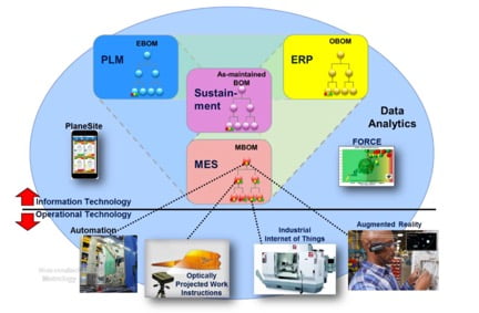
It improves the integration of systems data, facilitates automated data collection and dashboard metrics, and supports descriptive, predictive, and prescriptive analytics. It also connects factory equipment with the IT systems, driving efficient usage and secure data transfer.
Data security is one of the enabling technologies for the connected enterprise. This revolution is in its early stages but will rapidly drive industry to become more efficient in above-the-factory-floor functions.
Further, it will provide needed insight for continued productivity gains on the factory floor and in the supply base.
Lockheed Martin has already deployed a phone/computer application for aircraft on the production floor. It provides information about locations, schedule performance, part shortage, non-conformances, and other factors for every aircraft and component in work.
This pertains to not only those in the Fort Worth factory but also the aircraft and components in Italy and Japan. The application is being combined with a factory-wide part kit and tool radio frequency identification system (RFID). Ultimately, it will be able to automate updates of each aircraft on monitors located at each tool position with status and performance data.
Put in other words, a key way to understand the supply chain or the manufacturing support base is to see it from several optics.
The first optic is to see it from a more traditional supply chain perspective. Who are the major suppliers to the core sections of the aircraft assembled in Texas, Japan and Italy?
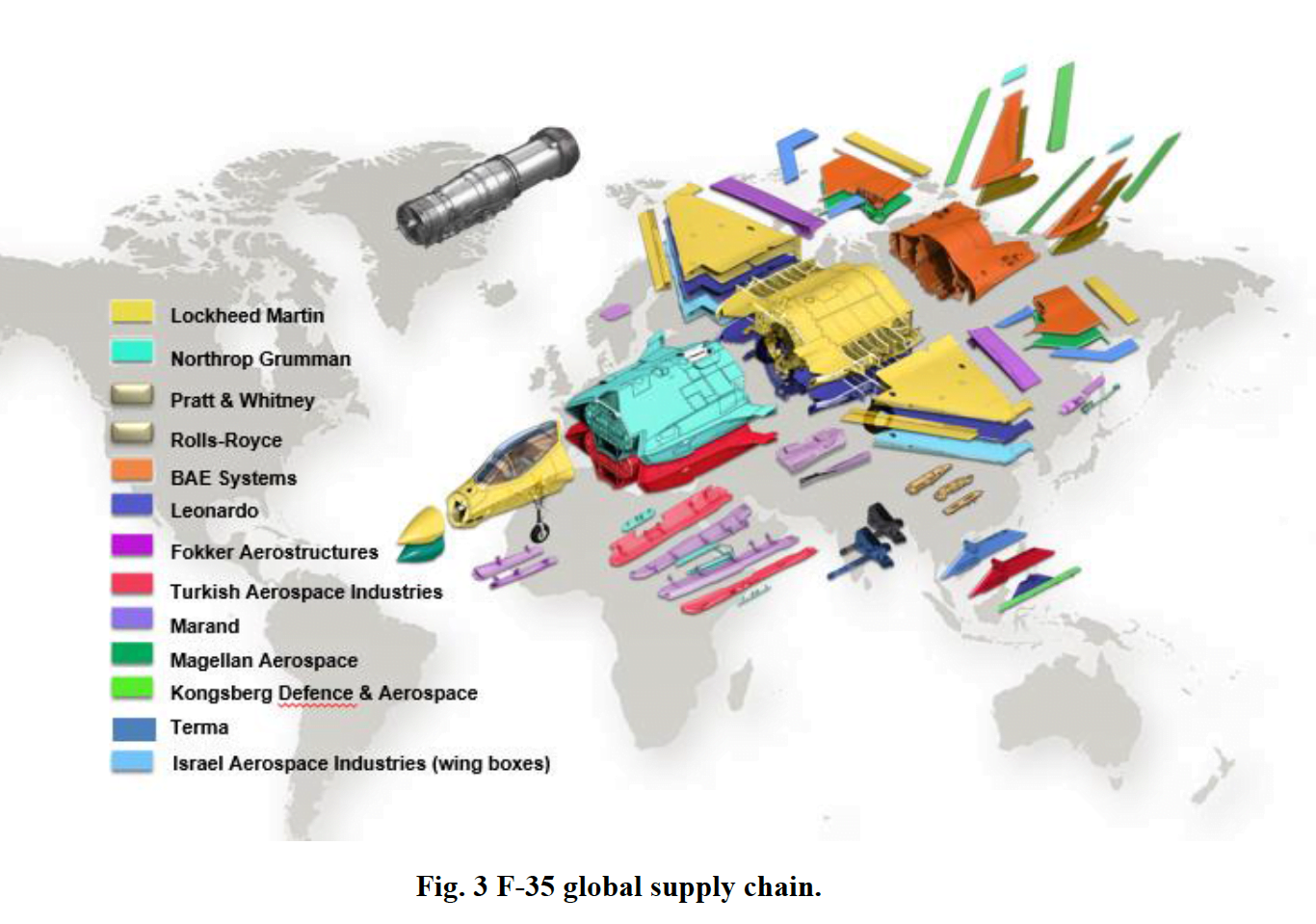
The second optic is to see it from a sustainability perspective whereby the performance of the parts in the field drive performance evaluations of the parts being supplied worldwide.
Performance can drive decisions with regard to global suppliers and lead to decisions to add global providers or shift from one provider to another.
The third optic is to look at the underlying man-machine providers for building the aircraft.
Here there is a broad participation of global producers for machines, tools and technologies, which can be folded into the production process.
Also, because of the digital nature of the production and sustainment process, commercial companies, which produce digital tools and capabilities, can be ported into the production and sustainment process as well.
At each level there are a variety of providers of parts, tools and capabilities to the production and sustainment process, much broader than if one simply stays at the level of the first optic.
For example, Fraunhofer which is a key player in Industry 4.0, is a part of the supply chain for the F-35 in terms of the third optic.
It is a whole new world for military aircraft production and sustainment. But the new world is a challenge to the acquisition, modernization and sustainment bureaucracies.
While they remain largely stove piped; the F-35 is not.
In this Defense News video, an interview with Don Kinard, Senior Fellow for F-35 Production, provides an overview on the production process used to deliver the F-35.
F35 Production from SldInfo.com on Vimeo.
Footnotes
- From the Fraunhofer report, Digitalized Manufacturing. Also, see the following https://www.iese.fraunhofer.de/en/innovation_trends/industrie40.html